HPC
Intel Skylake-SP Integrated I/O Architecture Implications for GPGPU/PCIe Connectivity
March 15, 2018
5 min read

There is a subtle but major change regarding PCIe I/O connectivity with the introduction of Intel's newest dual/quad processor CPU architecture, Skylake-SP. The architecture calls for the 48 PCIe lanes to be grouped in 3 separate pairs of 16 lanes per CPU coming from 3 separate IIO modules. In previous generations of CPU, the aggregate number of PCIe lanes would be associated with one IIO module.
The impact of this manifests itself in the inability to drive one single PCIe root complex per CPU, with a larger number of aggregate lanes as in previous CPU architectures. For example, with the Broadwell architecture, you could have a dual CPU system, and drive one PCIe root complex with 40 lanes of PCIe from each CPU. This is not possible with Skylake-SP. Each Skylake-SP CPU will have IIO #1 - 16 lanes, IIO #2 - 16 lanes, IIO #3 - 16 lanes. This means that even if all of the PCIe slots in the system were desired to be a part of a single PCIe root complex, the maximum amount of lanes from CPU ↔ PCIe fabric is 16 PCIe lanes.
This blog post may help get an understanding of PCIe root complex and the implications as well.


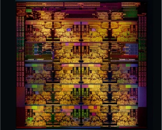
In this example, you can see that single the IIO is split into 3 separate 16 lane IIO segments. It limits how many PCIe lanes can feed a single root complex PCIe topology.

In this example, you can see that since Broadwell had a single IIO with all of the aggregate lanes. This creates more PCIe lanes that can be used to connect a single root complex PCIe topology.


There is a subtle but major change regarding PCIe I/O connectivity with the introduction of Intel's newest dual/quad processor CPU architecture, Skylake-SP. The architecture calls for the 48 PCIe lanes to be grouped in 3 separate pairs of 16 lanes per CPU coming from 3 separate IIO modules. In previous generations of CPU, the aggregate number of PCIe lanes would be associated with one IIO module.
The impact of this manifests itself in the inability to drive one single PCIe root complex per CPU, with a larger number of aggregate lanes as in previous CPU architectures. For example, with the Broadwell architecture, you could have a dual CPU system, and drive one PCIe root complex with 40 lanes of PCIe from each CPU. This is not possible with Skylake-SP. Each Skylake-SP CPU will have IIO #1 - 16 lanes, IIO #2 - 16 lanes, IIO #3 - 16 lanes. This means that even if all of the PCIe slots in the system were desired to be a part of a single PCIe root complex, the maximum amount of lanes from CPU ↔ PCIe fabric is 16 PCIe lanes.
This blog post may help get an understanding of PCIe root complex and the implications as well.
In this example, you can see that single the IIO is split into 3 separate 16 lane IIO segments. It limits how many PCIe lanes can feed a single root complex PCIe topology.
In this example, you can see that since Broadwell had a single IIO with all of the aggregate lanes. This creates more PCIe lanes that can be used to connect a single root complex PCIe topology.
